

PRODUCT · GUIDE
Microduck HD1910 DIY Robot Kit Guide
Compiled beginner guide for the HD1910 kit and individual parts. Not a revision-specific assembly, wiring or repair manual.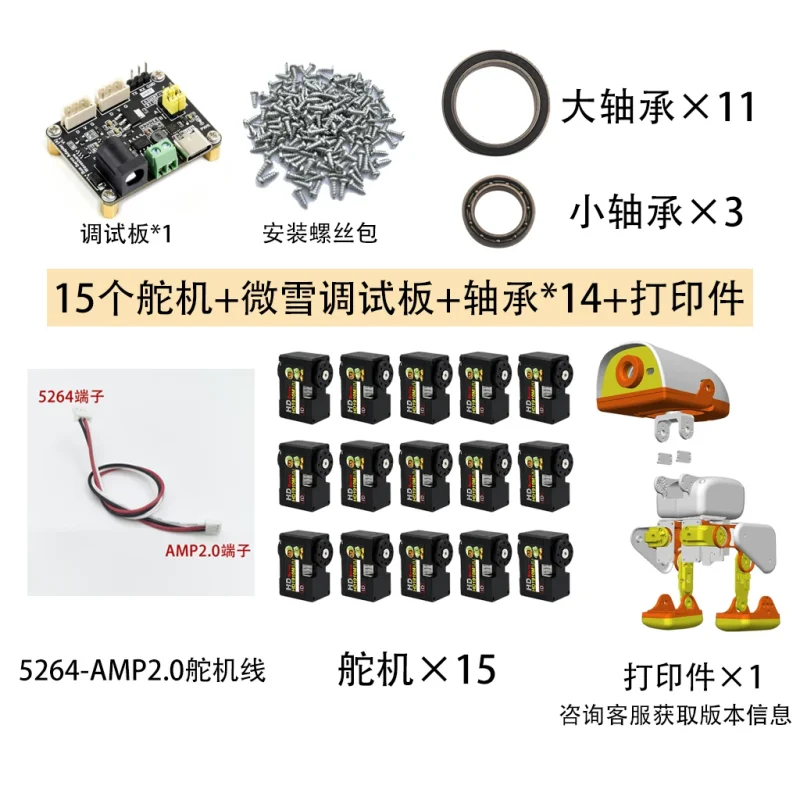
Assembly videos & project resources
Original maker videos and component documentation. Choose the HD1910 mechanical revision; project demonstrations may use electronics supplied separately.
01 Parts overview
Source: 机械行者Robo · Bilibili · 1:32. Copyright belongs to the original creator. Contact us for removal if this infringes your rights. Original video ↗ · Contact us
02 Lower leg assembly
Source: 机械行者Robo · Bilibili · 2:21. Copyright belongs to the original creator. Contact us for removal if this infringes your rights. Original video ↗ · Contact us
03 Upper leg assembly
Source: 机械行者Robo · Bilibili · 5:13. Copyright belongs to the original creator. Contact us for removal if this infringes your rights. Original video ↗ · Contact us
04 Torso assembly
Source: 机械行者Robo · Bilibili · 2:29. Copyright belongs to the original creator. Contact us for removal if this infringes your rights. Original video ↗ · Contact us
05 Neck assembly
Source: 机械行者Robo · Bilibili · 0:40. Copyright belongs to the original creator. Contact us for removal if this infringes your rights. Original video ↗ · Contact us
06 Head assembly
Source: 机械行者Robo · Bilibili · 5:50. Copyright belongs to the original creator. Contact us for removal if this infringes your rights. Original video ↗ · Contact us
OpenMicroDuck HD1910 training demonstration
Source: AI机器人极客 · Bilibili · 0:43. Copyright belongs to the original creator. Contact us for removal if this infringes your rights. Original video ↗ · Contact us
Videos play on this site. Original audio and on-screen text are retained; titles are translated for navigation.
Documentation, drawings & software
- HD-1910-C001 Feetech specification (8 pages)
- HD1910M dimensional drawing
- Robo maker assembly manual (21 pages, Chinese)
- HD1910 CAD, printing, component drawings & BOM
- Waveshare adapter A documentation & wiring
- OpenMicroDuck HD1910 structural differences
- Full project BOM (additional electronics)
- HD1910 servo setup and revision notes
- OpenMicroDuck software and training resources
- Raspberry Pi Camera Module 2 specifications
- Radxa ZERO 3 camera connection
01 · GUIDE
Choose the kit or an individual part
Check the edition selected in your order. The USD400 DIY mechanical kit contains 15 HD-1910-C001 servos, printed parts, an M2 screw pack and 14 bearings. Single servos, URT-2 boards, printed parts, Bus Servo Adapter (A) boards and bearing sets are separate options. The camera is not available to buy. Assembly renders and conceptual diagrams do not mean every pictured electronic component is included.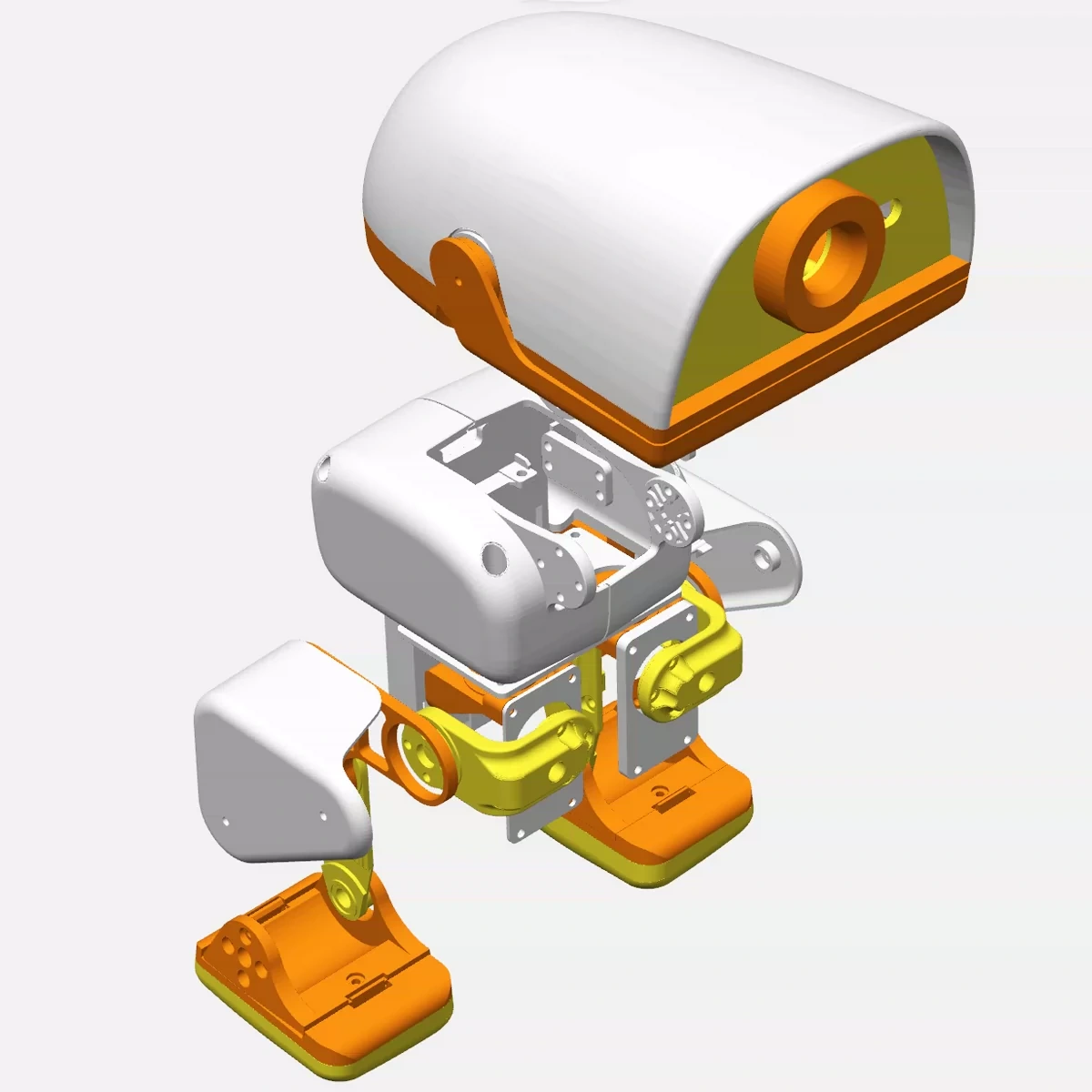
02 · GUIDE
Unpack and check the delivery
Check the selected option before assembly. The USD400 kit includes 15 HD-1910-C001 servos, Microduck printed parts, an M2 mounting screw pack, 14 bearings (11 large + 3 small), a Waveshare bus-servo adapter/debug board and a 5264-AMP2.0 servo cable. The single-servo option supplies one servo; the printed-parts option does not include servos. Compare the received parts with your order before powering anything. Contact support for a revision mismatch or missing parts. Controller, camera, IMU, storage and power system are separate.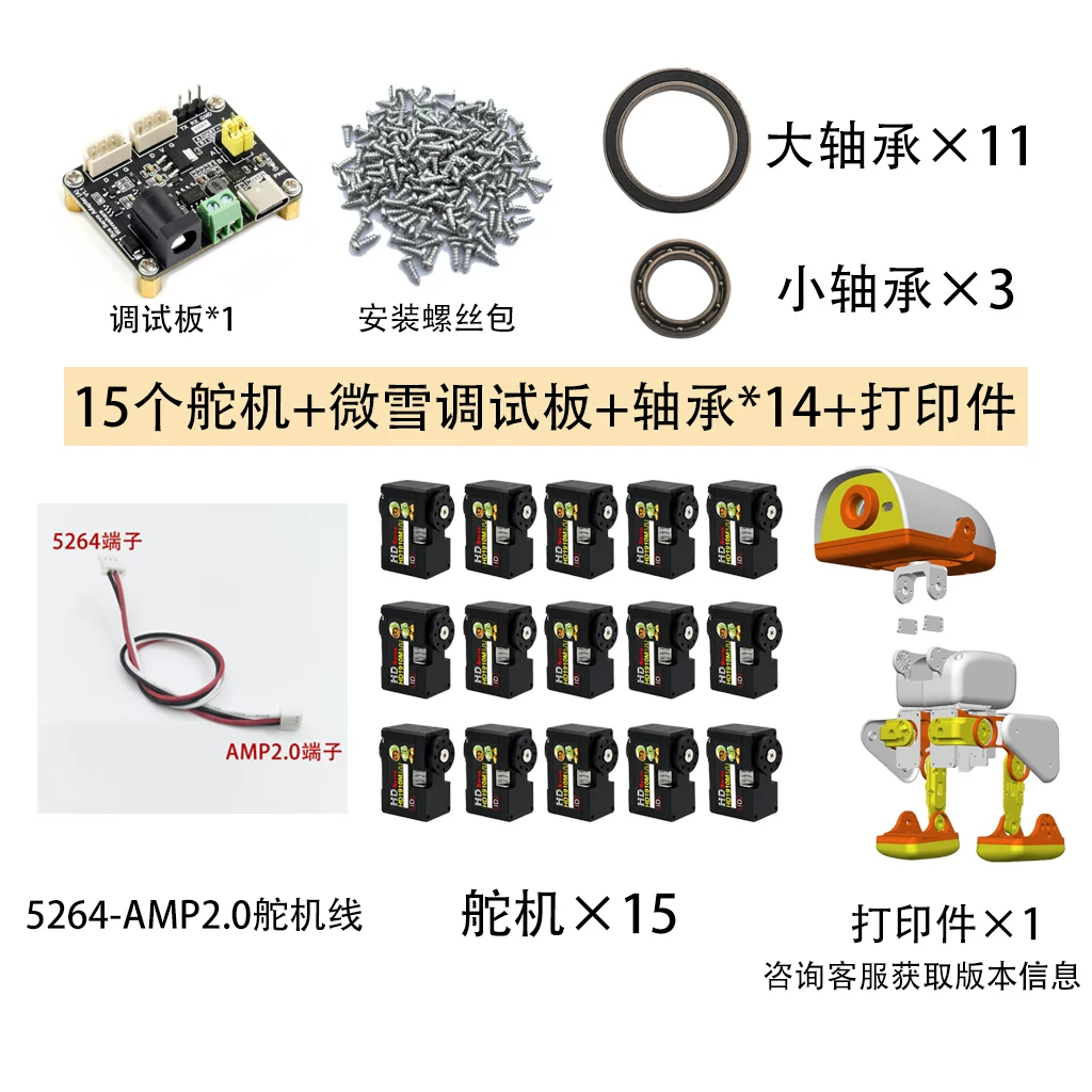
03 · GUIDE
Prepare a safe workspace
Use a level, nonslip, well-lit workbench and separate the screws and bearings. Disconnect all power before mechanical assembly or cable changes. Keep fingers, hair and clothing away from joints. Do not hold powered joints or force the servos rapidly by hand. Robot assembly and commissioning skills are needed. Keep initial tests supervised and provide a quick way to disconnect power. Choose HD1910-compatible CAD before printing: XL330 and HD1910 horn interfaces differ. The linked maker repository separates the Feetech and XL330 revisions. Its 21-page manual and component diagrams are assembly references; match them to the supplied printed-part revision.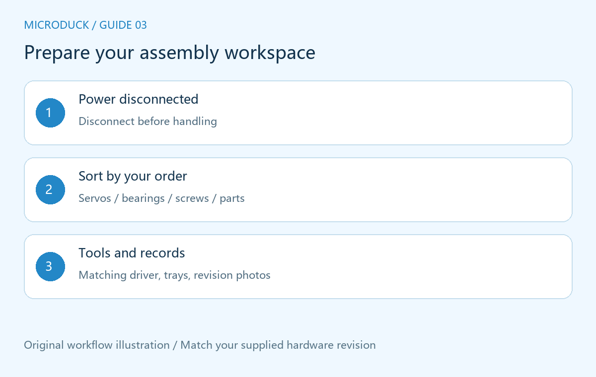
04 · GUIDE
Match the mechanical revision
This product follows the HD1910 route. Public project documentation describes different horn interfaces on XL330 and HD1910 hardware; do not mix printed parts from different routes. Compare the actual parts, mounting holes and supplied assembly instructions before fitting bearings or joints. The conceptual diagram identifies component groups; it is not a screw-length, torque or step-by-step assembly drawing. Contact support if revision-matched drawings are unavailable.
05 · GUIDE
Inspect servos and mechanical joints
Check that servo labels match HD-1910-C001 in your order. Inspect shafts, holes, connectors and housings for transport damage. Fit joints loosely first, check free movement and cable routing, then tighten according to the matching assembly instructions. Do not force long screws or power a binding joint. Stop and photograph any interference; do not cut or grind parts before obtaining guidance.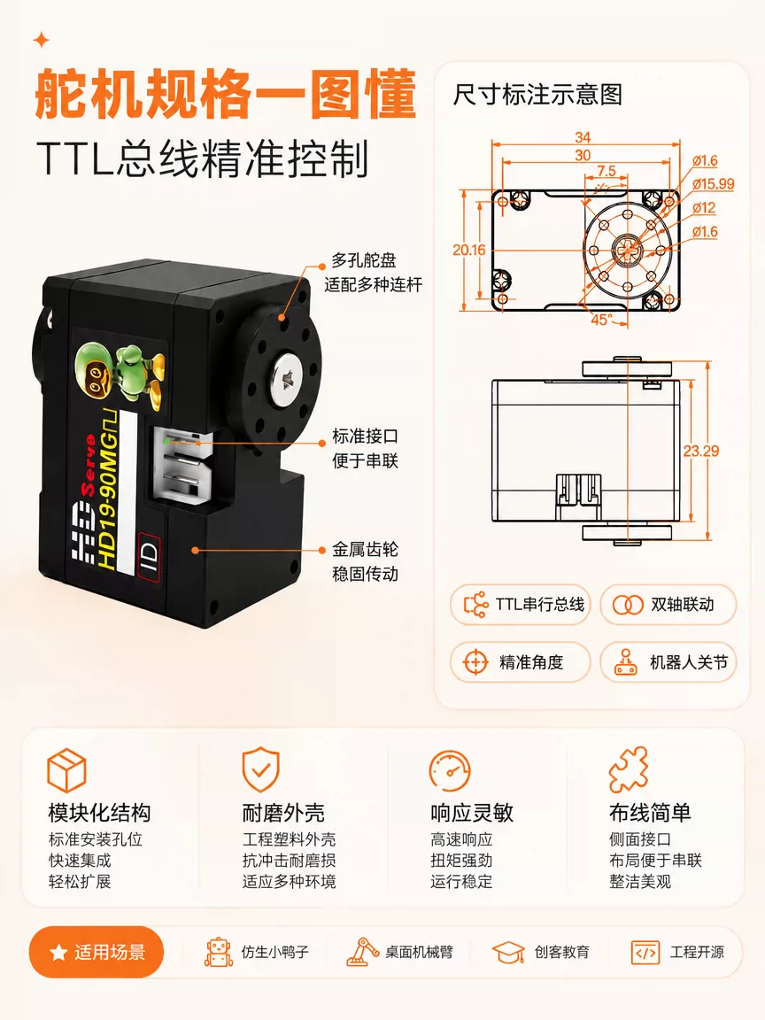
06 · GUIDE
Controller and power are separate
A mechanical kit is not a complete electronic control system. Choose the controller, storage, IMU, camera, battery and power adapter for your project separately; debugging and adapter boards also have individual options. Seller artwork specifies 4–8.4V for the servo only. This is not the supply rating of every robot interface. Check the actual board and power labels, polarity, connector and pin assignments before connecting anything; similar connectors do not prove compatibility. The supplied Waveshare adapter has no voltage regulator: its servo output follows the input. The HD1910 specification allows 4–8.4V; do not copy 9–12.6V examples intended for other servo families. See the board manufacturer documentation before selecting supply and USB/UART mode.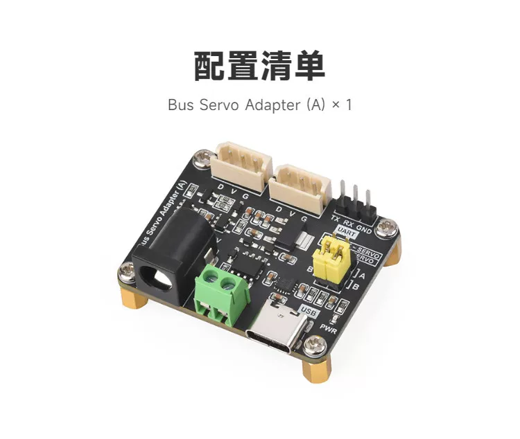
07 · GUIDE
First communication and calibration
Use software and protocols matching your servos and control board. Support the mechanism securely, unload the joints and keep power disconnect accessible. Start with read-only status checks, then follow revision-matched instructions for IDs, zero offsets and limits. Do not copy another robot’s offsets, target angles or firmware settings. Calibration and firmware changes may persist; do not write settings or flash firmware without matching instructions and an original configuration backup.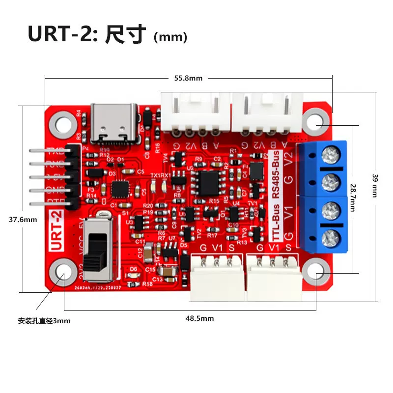
08 · GUIDE
Development resources and limits
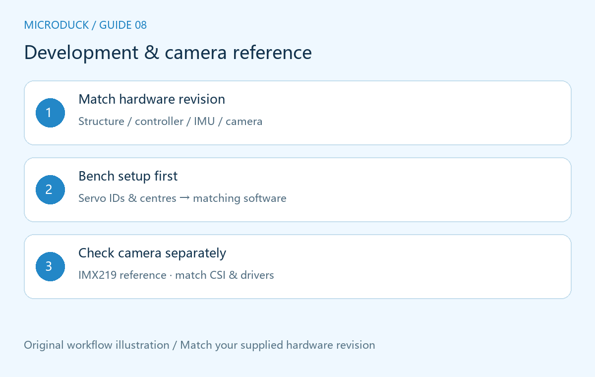
OpenMicroDuck and HD1910 replica projects provide learning material for mechanics, software and training, with hardware and revision differences. Booting software, running a policy and verifying actual walking are separate milestones. Check your power system, IMU orientation, joint calibration and protection before enabling motion. Public project demonstrations do not certify the same walking or autonomous features on this kit.Camera reference: OpenMicroDuck uses an IMX219/CSI route. Raspberry Pi Camera Module 2 uses an 8 MP IMX219 sensor (3280 x 2464); Radxa documents this module for ZERO 3. The project BOM also lists 5 MP, conflicting with the manufacturer specification. These references do not identify the unconfirmed camera sold here. Confirm the controller, module part number, ribbon pin count/orientation/pitch and mounting before ordering; connect with power off and never plug CSI into a servo TTL port.
09 · GUIDE
Troubleshooting and stopping
No connection: disconnect power, then check the board, driver, protocol, supply and pin assignments; avoid repeated live reconnects. Shaking or binding: unload and disconnect power, then check mechanical clearance, supply and offsets. Parts or bearings do not fit: check the mechanical revision and contact support rather than forcing them. Stop after unusual smells, heating, hot cables or repeated restarts; record the problem instead of adding load.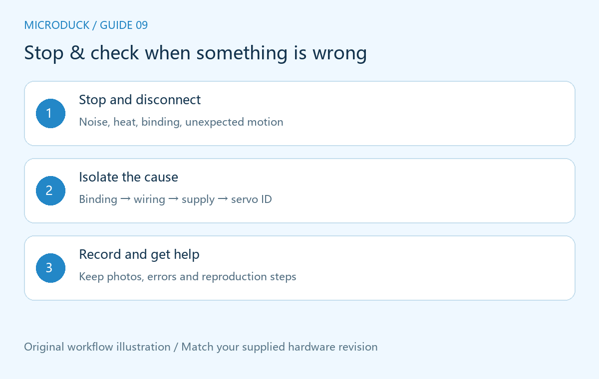
10 · GUIDE
Care, service and guide scope
Keep parts clean and dry, secure moving joints for transport and disconnect power before disassembly. Zoowai provides a one-year warranty for non-user-caused faults; other repairs are chargeable and the customer pays repair shipping. Send the ordered edition, part labels, photos, power and software versions and symptoms to support; do not send account passwords. This Zoowai compiled beginner guide draws on product material and public technical references. It is not an original complete-robot manual or a substitute for matching assembly, wiring or repair documentation.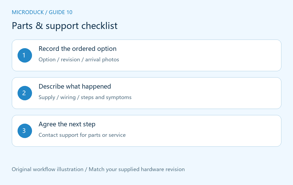
NEED MORE HELP?